Automatic Self Calibration
1. Overview
The Automatic Self Calibration System is a next-generation, plug-and-play spatial alignment tool within the HoloMIT SDK. It seamlessly bridges the gap between the physical VR space and the volumetric capture space without requiring manual slider adjustments or physical orb manipulation.
By leveraging an Open Source Machine Learning (ML) pipeline, the system can instantly "understand" the user's volumetric pointcloud. The automatic_self_calibration.dll evaluates the ML model across all connected cameras to ultimately select the best one. When triggered, the system matches the user's virtual head and hands to their physical VR tracked devices (HMD and Controllers) to perform a perfect, instant spatial alignment.
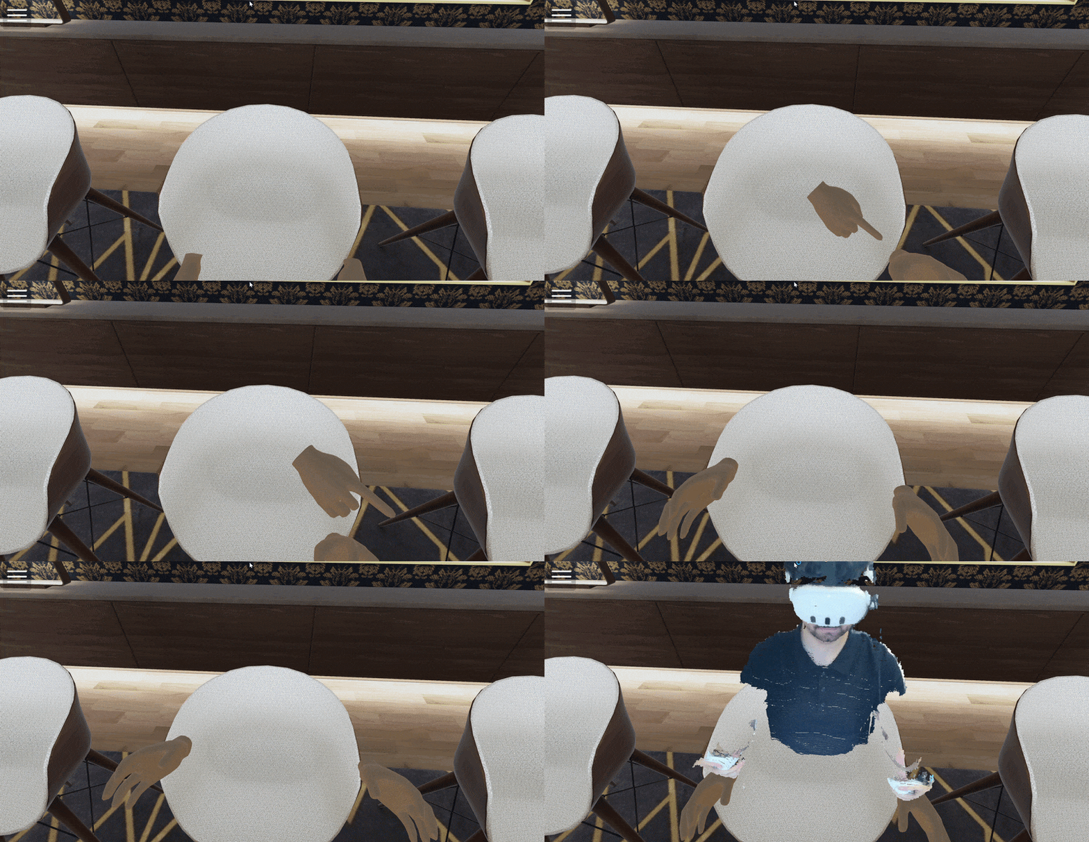
Figure 1: Automatic Calibration Overview
2. Triggering the Calibration
To ensure the calibration happens exactly when the user is ready and standing within the camera's optimal field of view, the process is initiated via the User Interface rather than direct hardware input.
2.1. Unified Menu System & AutomaticCalibrationController
The entire calibration flow is centralized within the AutomaticCalibrationController component. This controller handles requests to the internal HoloCapturer.dll, which in turn manages the process with the automatic_self_calibration.dll and the ML model.
In the provided Automatic Self Calibration Sample, users trigger the process through a button in the Unified Menu System. Pressing this button initiates a 3-second countdown. This gives the user time to step back, position themselves correctly, and ensure that at least one of the cameras can see them clearly before the snapshot is taken.
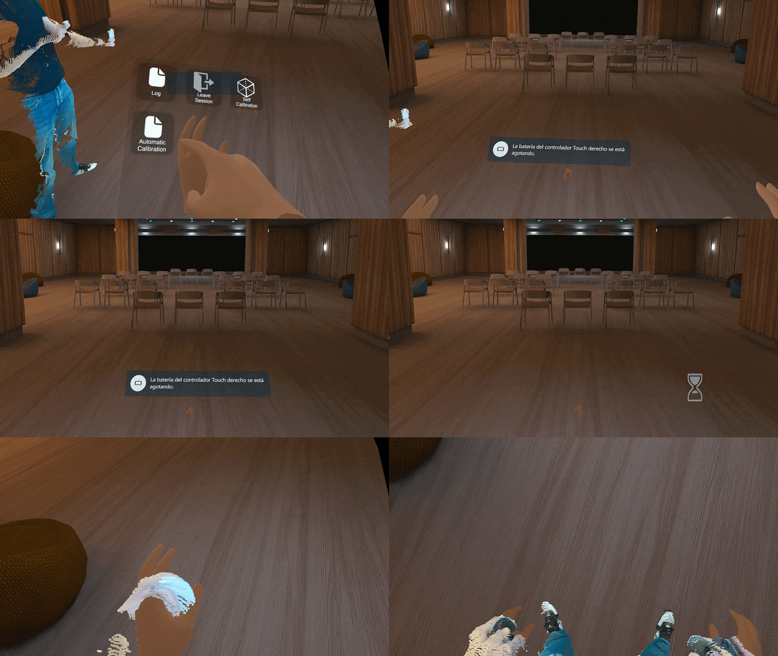
Figure 2: Unified Menu System Calibration Button and Countdown
3. The ML Pipeline
Once triggered, the HoloMIT Capturer delegates the visual recognition task to the Machine Learning model to find the corresponding volumetric points.
3.1. 2D Pose Estimation
The captured RGB color frame is fed into the ML model. The model identifies the user's joints and extracts the 2D pixel coordinates (U, V) of three critical reference points:
- Head: Nasal bridge (tabique nasal) for the VR headset. The system uses the tracked device pose in Unity to establish the virtual vector.
- Left Hand: Index finger on the left controller.
- Right Hand: Index finger on the right controller.
While the VR headset obscures the nasal bridge from the camera's view, the ML model is still capable of accurately estimating its exact position.
3.2. 3D De-projection
Because the camera SDK hardware-registers the color frame to the depth map, the system takes those three 2D pixels and queries their exact Depth (Z) values. Using the camera's intrinsic parameters, these pixels are de-projected into 3D Local Space, giving us the exact spatial coordinates of the volumetric head and hands.
3.3. Customizing the ML Model
The ML pipeline is configurable via a config.json file. This file allows you to change the underlying ML model used during calibration.
To change the model, you simply modify the model_folder_name property:
{
    "__model_foler_name__": "rtmw-x | rtmw-m",
    "model_folder_name": "rtmw-m"
}
By default, the HoloMIT SDK currently ships with the rtmw-m model. While other variants exist (such as rtmw-x), they are significantly heavier and are not included out-of-the-box to optimize performance and reduce build sizes.
Important Directory Structure:
If you decide to use a different model, the system requires a strict directory structure. The new model must be placed inside a folder matching the exact name you specified in the config.json. Furthermore, the model file inside that folder must be named end2end.onnx.
4. The Alignment Math
At this stage, the system has two isolated sets of 3D points (Triangles):
- Set A (Virtual/Volumetric): The 3 points extracted via the ML model.
- Set B (Physical/VR Tracking): The 3 points extracted from the HMD and Controllers.
To perfectly overlap Set A onto Set B, the SDK utilizes a highly optimized, constrained version of the Kabsch-Umeyama Algorithm.
4.1. Translation (Full XYZ)
The algorithm calculates the geometric center (Centroid) of both triangles. It then applies a complete 3D translation (X, Y, Z) to move the volumetric dataset so its center perfectly matches the center of the user's physical VR tracking space.
4.2. Rotation (Strictly Y-Axis / Yaw)
Standard Kabsch algorithms align objects across all three rotational axes. However, doing so could cause the volumetric mesh to tilt (Pitch/Roll) if the user is holding one hand slightly higher than the other during calibration, causing a loss of perceived gravity.
To prevent this, the HoloMIT SDK constrains the rotation strictly to the Y-Axis (Yaw). The algorithm mathematically projects both triangles onto the XZ ground plane and calculates the optimal horizontal rotation. This ensures the volumetric capture faces the exact same direction as the physical user while keeping the floor perfectly level.
4.3. Note on Scaling
The Umeyama extension of the Kabsch algorithm inherently supports calculating scale differences between two point sets. However, scaling is deliberately disabled in this implementation. Because we are using professional-grade depth sensors, the volumetric data is natively captured in true 1:1 real-world scale. Calculating and applying a scale multiplier is unnecessary and could distort the physical accuracy of the hologram.
5. Setup Guidelines & Common Pitfalls
To ensure a flawless automatic calibration, developers and users should keep the following guidelines in mind:
- Camera Visibility: The user MUST have both their head and hands clearly visible within the camera's Field of View during the 3-second countdown. If a hand is occluded or outside the frame, the ML model will fail to generate an accurate triangle, and the calibration will abort.
- W-Pose Recommendation: While the user does not need to stand in a rigid T-Pose, it is highly recommended to hold the controllers up and away from the torso (e.g., a "W" pose) when the countdown finishes. This makes it significantly easier for the ML model to distinguish the index fingers and nasal bridge from the rest of the body.
In situations where the lighting is incorrect or if the points are misinterpreted, the model might fail. If this happens, you should restart the automatic calibration process. Try to improve your position, always ensuring that you are within the optimal angle of the maximum number of connected cameras.
Important for Meta Quest 3 Users: If you are using a Meta Quest 3 (or similar standalone devices), you may need to recenter your view just before auto-calibrating. This is because the headset can lose its virtual world positioning when taken off and put back on. For best results, reset your view and ensure your Guardian boundary is correctly set up.
6. Step by Step Implementation
Step 1: Core Components
The Automatic Self Calibration functionality is natively integrated into the same UI panel as the manual Self Calibration within the samples provided in the SDK.
However, you are not strictly tied to this UI. The core functionality is driven by the Automatic Calibration Controller component, which comes pre-compiled in the Pilots DLL. This means you can invoke the calibration process directly from your own custom code.
When setting up this component in the Unity Inspector, you must define the following parameters:
- VR Trackers: You need to assign the
VR_HMD,VR_LHand, andVR_RHandTransform references. These should point directly to your player's tracked devices so the system knows where the physical body is located in the virtual space. - IsCalibrating: This is a read-only boolean state flag. It returns
truewhile the system is actively waiting for a countdown or waiting for the asynchronous native DLL to return the calculation. - Calibration Delay: Found internally as
m_CalibrationDelay, this sets the amount of time (in seconds) the system waits before snapping the capture.
To trigger the process via code, you have a few options:
RequestAutomaticSelfCalibration: This is the core function. It immediately captures the current tracker positions and calls the DLL to perform the Machine Learning evaluation asynchronously.TriggerAutomaticCalibrationWithCountdown: A helpful wrapper function that utilizes them_CalibrationDelayvariable to perform a progressive countdown before eventually invoking the core calibration request.
Whenever the Machine Learning DLL is invoked, the Unity component will automatically draw debug spheres in the Scene view to help you visualize exactly where the ML model has recognized the key body points.
Step 2: Custom UI and Countdown Logic
If you decide to build a custom UI (or explore the SDK's CalibrationUIBridge), you will likely want to link your UI to the countdown logic. In our SDK, the UI bridge component calls a function (like TriggerAutomaticCalibration) which serves as a streamlined entry point to the core RequestAutomaticSelfCalibration logic mentioned above.
To replicate a clean UX flow:
- Create the UI Elements: Set up a Canvas with a calibration trigger Button and a Text element to display the countdown numbers.
- Wire the References: Your custom UI component needs references to the automatic calibration controller, the trigger button, and the text element.
- The Countdown Flow:
- When the user presses the button, hide the button and activate the text element.
- Start the countdown using the controller's delay variable, updating the text element each second.
- Once the countdown reaches zero, change the text to indicate that the system is processing (e.g., "Calculating...").
- Monitor the
IsCalibratingflag. While it istrue, wait for the background processing to finish. - Finally, re-enable the button and hide the text element once
IsCalibratingbecomesfalse.
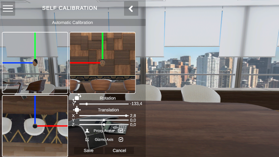 Figure 3: Example of a custom UI before triggering the automatic calibration on desktop mode.
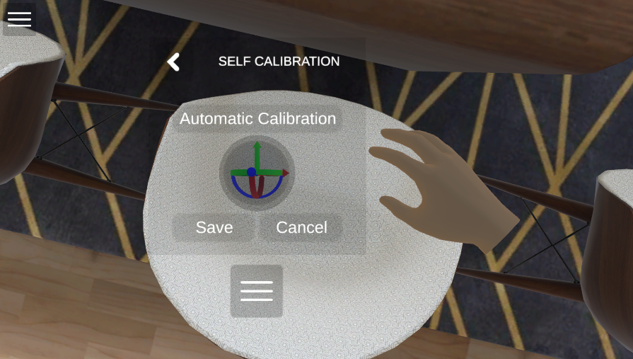 Figure 4: Example of a custom UI before triggering the automatic calibration on VR mode.
Step 3: Debugging and Fallbacks
The controller also provides a couple of extra utilities for troubleshooting and fallback scenarios:
TriggerDebugDetectCalibration: This function does not apply any movement to the volumetric mesh. Instead, it only captures the frame and draws the debug spheres in the Unity scene, showing the exact points detected by the ML model. It is extremely useful for verifying camera coverage and lighting without affecting the user's calibration.
TriggerUnityKabschCalibration: In the rare case that the native automatic_self_calibration.dll fails to calculate the alignment properly, this function acts as a Plan B. It performs the exact same Kabsch alignment algorithm using Unity's C# logic rather than relying on the native C++ counterpart.