Self Calibration
1. Overview
The Self Calibration System is a built-in spatial alignment tool within the HoloMIT SDK. It allows users to manually calibrate and align their volumetric representation (the HoloCapturer GameObject) to their physical body or tracked devices.
It seamlessly supports both pre-recorded datasets and real-time live streams (ranging from a single camera up to full-body N-camera setups). The system provides three distinct interaction paradigms:
- Desktop (2D PC): A UI-driven approach using mouse input and sliders.
- Virtual Reality (VR): A Direct User Control approach using a physical, logarithmic spatial orb.
- Debug/Hardware Input: A robust fallback system utilizing direct keyboard shortcuts and gamepad joysticks.
Important Prerequisite: The calibration panel can only be activated if the user enters with a UserRepresentationType set to HoloCapturerDepth. If you enter the session with a non-volumetric representation (such as "none" or an avatar), the system will prevent access to the calibration tools, as there is no volumetric data to align.
2. Step by Step Implementation
Step 1: Necessary Prefabs and Scripts
Before we begin, we need to introduce the prefabs and scripts that will be used.
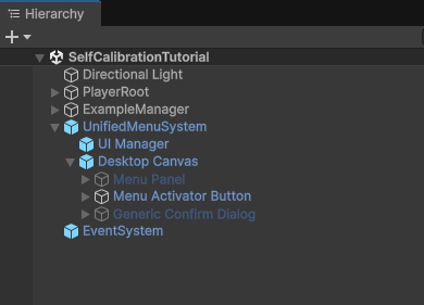
UnifiedMenuSystem.prefab: This is a UI prefab (Unified Menu System) used across the SDK. While not strictly mandatory for self-calibration, it is highly recommended as it comes with self-calibration already integrated as an example within theSystem Menu Controllerscript in itsUI ManagerGameObject.Event System: This prefab is strictly necessary because it contains theXR UI Input Modulescript (which inherits directly from Unity'sInput System Module). This allows us to have a unified UI input system for both PC (keyboard and mouse) and VR.
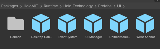
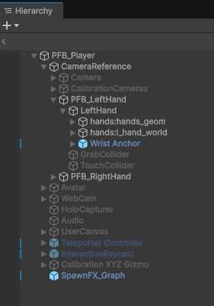
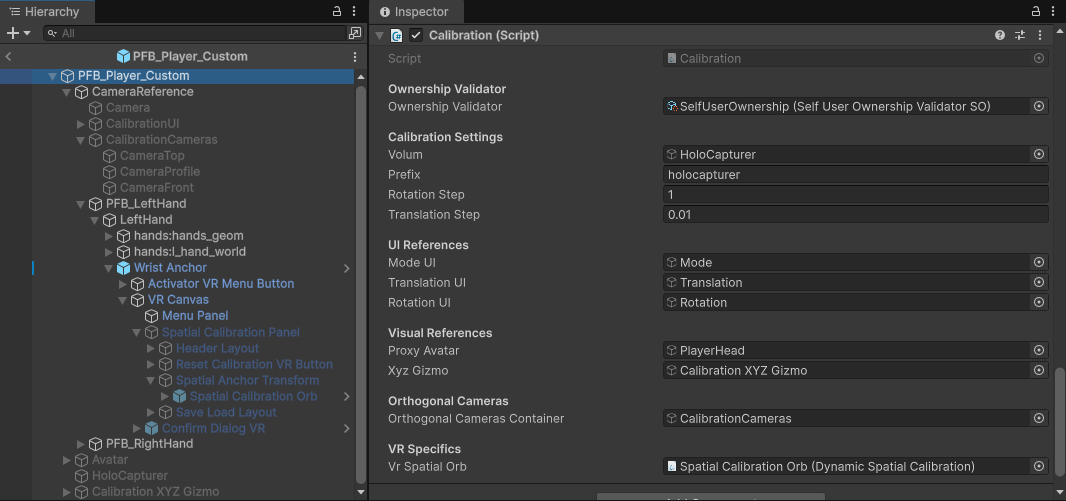
PFB_Player: This prefab contains several crucial components required for self-calibration. We understand that each project may have its own custom player, so here are the specific components needed for self-calibration:Calibration: Located on the root object (PFB_Player).Wrist AnchorPrefab: Located on the left hand, it provides access to the spatial calibrator.Calibration XYZ GizmoGameObject: A visual reference object that can be enabled for better axis visibility, located as a child of thePFB_Player.AvatarGameObject: Also a child of thePFB_Player, containing theTracked Device Posecomponent (indicating the position of the VR headset).Calibration CamerasGameObject: A child ofCamera Reference, containing the cameras displayed in the Unified Menu System -> Desktop Canvas -> Self Calibration Panel.
Step 2: Setting Up Menu and Pilot Scenes
Once we have a clear understanding of the necessary elements, the first step is to set up your menu scene and pilot scene to create a session. For detailed instructions on how to proceed, please refer to the Quick Start Guide.
Remember to add these scenes to the Build Profiles in Unity; otherwise, the system will not be able to find them at runtime.
Step 3: Adding Base Prefabs to the Scene
With your scenes configured, the next step is to add the calibration functionality. Drag and drop the Unified Menu System and Event System prefabs into the scene you wish to calibrate. Make sure to check the Inspector to ensure there are no missing references.
Step 4: Setting Up the Player and Calibration Component
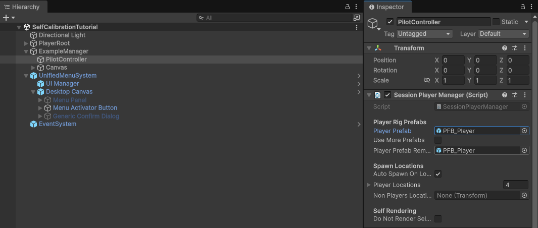
Now it's time to set up the Player. If you are using the default player provided with the HoloMIT SDK, simply add the PFB_Player to your SessionPlayerManager component within the session scene (if it isn't assigned already).
If you prefer to add the self-calibration components manually to your custom player, follow these steps:
- Attach the
Calibrationcomponent (provided inPilots.dll) to your player's root GameObject. - Fill in the serialized parameters in the Inspector:
- Ownership Validator: Assign an ownership validator (you can find the
Selfvalidator inPackages/HoloMIT/Runtime). This ensures only the correct user can calibrate their representation. - Volum: Assign the
HoloCapturerGameObject here. This is the actual volumetric representation that you want to calibrate. - Prefix: A string used for saving/loading the calibration data locally (e.g., "holocapturer").
- Rotation Step / Translation Step: Values determining the sensitivity of adjustments.
- UI References: Assign the respective UI GameObjects for the mode, translation, and rotation panels (Note: these UI elements in
CalibrationUIare intended for debug purposes). - Visual References: These provide a reference point during calibration. You can copy them from
PFB_Playerif needed.- Proxy Avatar: A dummy avatar used as a visual reference. This avatar needs a
Tracked Device Posecomponent to capture the VR Headset's position. - XYZ Gizmo: A GameObject representing the 3D axes for visual guidance.
- Proxy Avatar: A dummy avatar used as a visual reference. This avatar needs a
- Orthogonal Cameras: You can duplicate the
Calibration CamerasGameObject from thePFB_Playerand assign it here. This contains the Top, Front, and Side cameras used in the UI. - VR Specifics (Dynamic Spatial Calibration): The spatial orb reference for VR (explained in Step 5).
Step 5: Configuring the VR Spatial Orb
Finally, to set up our spatial orb for VR calibration:
- Locate the Left Hand GameObject of your VR player and attach the
WristAnchorprefab as a child. - On the
Wrist Look Detectorcomponent of theWristAnchor, assign your VR Camera's Transform. This allows the menu to activate only when you look at your wrist. - Navigate through the hierarchy to
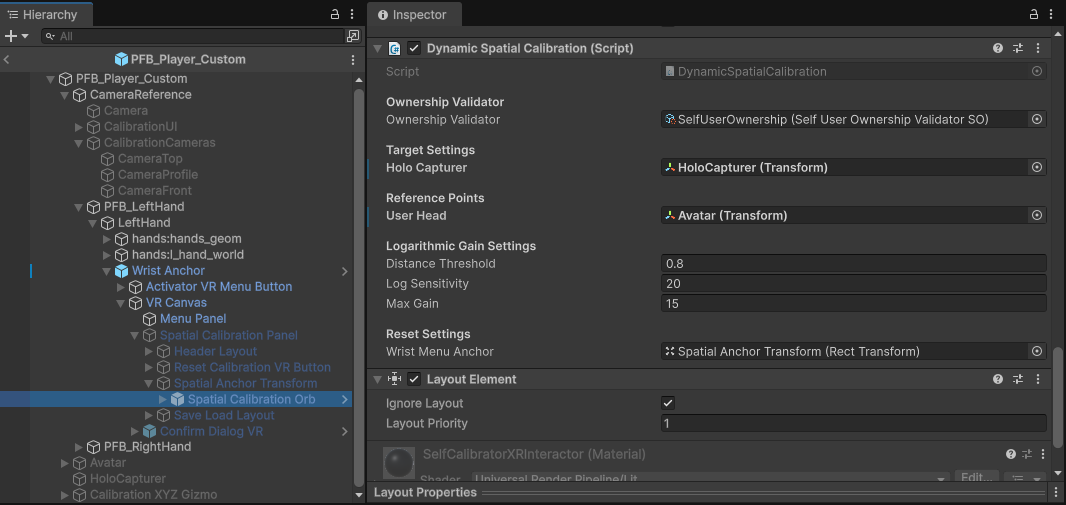
VR Canvas -> Spatial Calibration Panel -> Spatial Anchor Transformto find theSpatial Calibrationprefab. - On its
Dynamic Spatial Calibrationcomponent, you must assign:- The
HoloCapturer(the same volumetric representation assigned in theCalibrationcomponent). - The
Avatarreference (User Head) to track the user's position.
- The
Even if you are using the default PFB_Player provided in the SDK, you must manually assign these two references (HoloCapturer and User Head) on the Dynamic Spatial Calibration component within the Spatial Calibration prefab.
3. Core Backend & State Machine (Calibration.cs)
At the heart of the calibration module is the Calibration instance. This backend manages data persistence, visual aids, and most importantly, a strict State Machine.
3.1. The State Machine Architecture
To prevent accidental overwrites or "phantom writes" to the disk, the system rigidly controls what the user can do based on their current state:
ComfortState: Calibration is entirely OFF.CalibrationModeState: The main menu of the calibration system is open, but no active editing is happening.TranslationState: The user is actively moving theHoloCapturerin XYZ space.RotationState: The user is actively rotating theHoloCapturer.
Data Protection: The system will only allow saving (Save) or discarding (Load) data if it detects that the user is currently in an active editing state (TranslationState or RotationState).
3.2. Visual Aids
To assist the user during calibration, the backend can toggle specific visual helpers via the UI or input:
- Proxy Avatar: A standard 3D dummy avatar that mimics the tracked device's position, giving the user a 1:1 reference of their physical body in virtual space.
- Gizmo System: Visual axis indicators (XYZ Arrows/Rings) that show the orientation of the volumetric data.
- Orthogonal Cameras: Specific camera views (Top, Front, Side) activated during calibration to help judge depth and alignment accurately.
4. Desktop Calibration Module (UI Driven)
The Desktop calibration is accessed via a dedicated UI panel (e.g., triggered by a button created via the Unified Menu System) and acts as a bridge to the Calibration. backend using the CalibrationUIBridge.
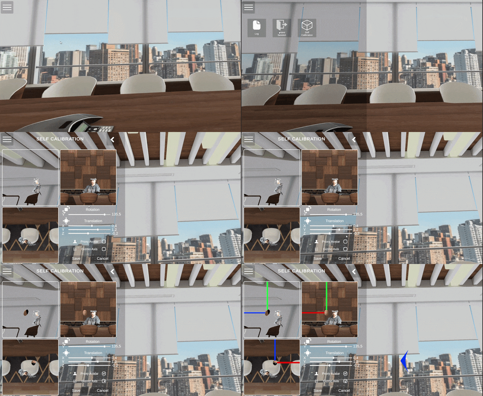
Figure 1: Example of a user interacting to reach the UI Desktop Self Calibration System.
4.1. UI Interactions
- Sliders & Input Fields: The panel provides granular control over the
HoloCapturer's Transform. Users can adjust the X, Y, and Z positions, as well as the Y-axis rotation. Adjusting a slider automatically forces the State Machine into the correct editing state. - Visual Toggles: Checkboxes allow the user to enable the Proxy Avatar and Gizmos to visually overlap the volumetric mesh with the tracking origin.
// Example of how the UI Bridge forces the state and updates the Transform
public void SetTranslationXFromUI(float _value)
{
    // Ensure we are in editing mode before applying values
    EnsureCalibrationState(typeof(TranslationState));
    Vector3 pos = context.VolumTransform.localPosition;
    context.VolumTransform.localPosition = new Vector3(_value, pos.y, pos.z);
}
4.2. Collaborative Calibration (Asymmetric Setup)
Because the UI architecture is built on top of the Unified Menu System, the Desktop and VR interfaces are completely interconnected and share the same backend data.
This is extremely useful for asymmetric collaborative setups: if a user is currently wearing the VR headset and struggling to align themselves, a second person (or operator) can use the Desktop UI to adjust the VR user's volumetric representation in real-time, effectively calibrating them from the outside.
5. VR Calibration Module (Spatial Orb)
Unlike the Desktop version, the VR calibration utilizes Direct User Control via the DynamicSpatialCalibration component. When the user opens the Self Calibration panel on their VRWristMenuView, a physical interactive "Orb" spawns.
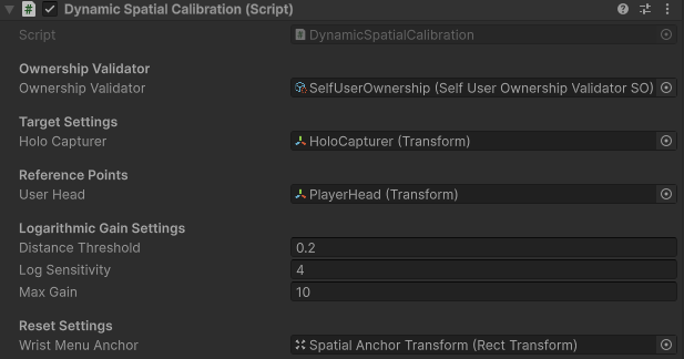 Figure 3: The DynamicSpatialCalibration component in the Inspector, showing the Target Settings and Logarithmic Gain variables.
5.1. Direct Physical Interaction
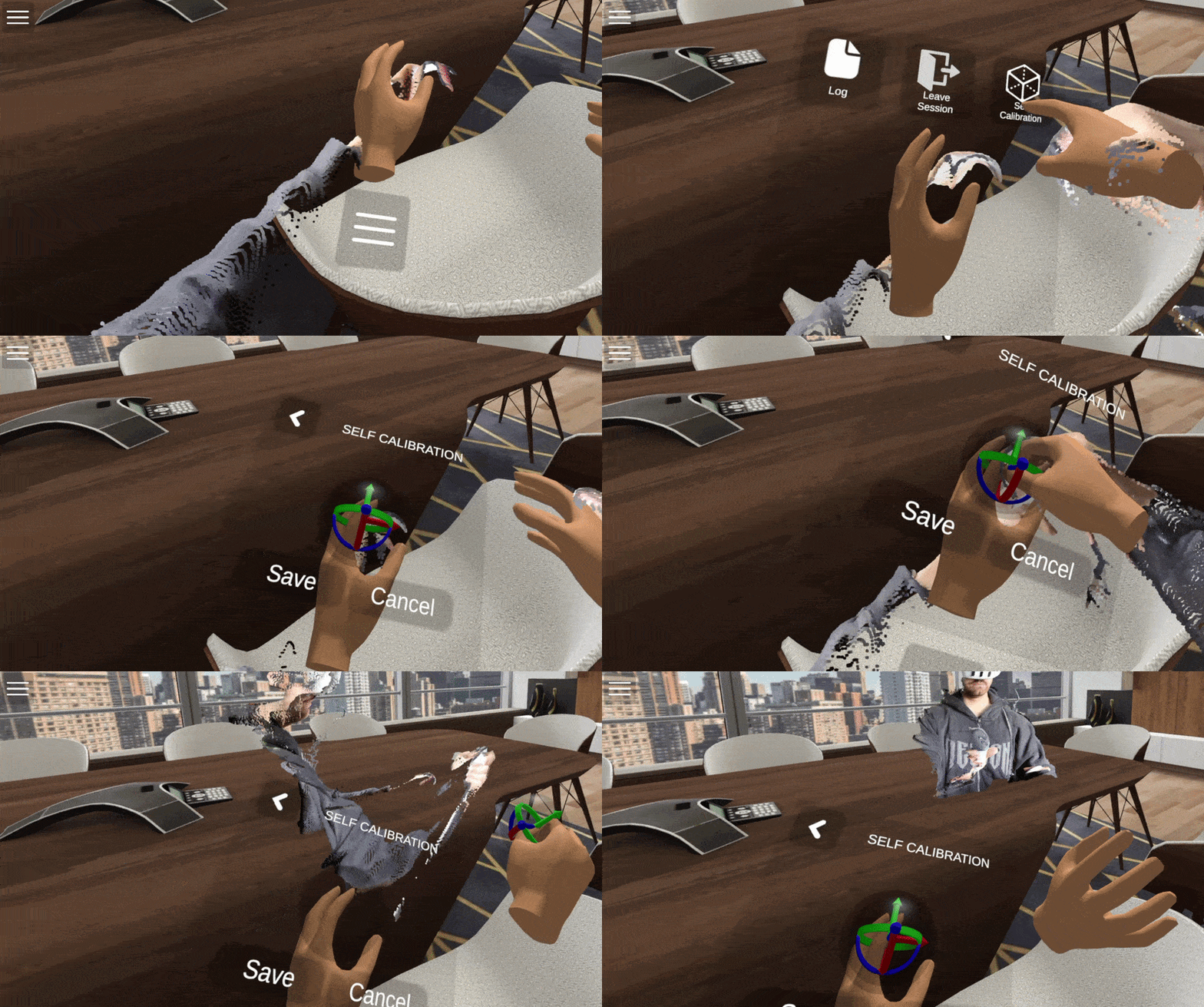
Figure 4: Demonstration of a user interacting with the UI to reach the Self Calibration System.
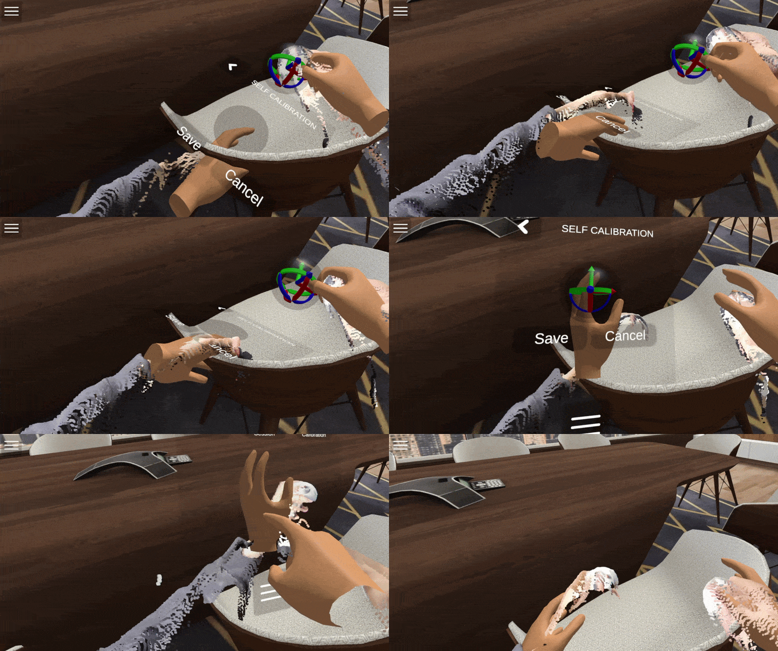
Figure 5: Demonstration of a user manually calibrating their volumetric representation using the spatial orb.
The user grabs the Calibration Orb (typically with the right hand using the Grabbable component).
- Translation: Moving the orb physically moves the
HoloCapturerin XYZ space. - Rotation (Y-Axis Lock): Twisting the orb physically rotates the
HoloCapturer, but only on the Y-axis (yaw). Pitch and roll are locked via code to prevent breaking the volumetric orientation. - Auto-Return (OnRelease): When the user releases the orb, the SDK instantly returns it to its initial starting position. This replaces the old manual "Reset" button, ensuring the orb is always within reach after an adjustment.
5.2. Logarithmic Depth Algorithm
To solve the UX problem of moving a volumetric object that might be far away, the orb uses a Natural Logarithm ($\ln$) Gain System.
The further away the HoloCapturer is from the orb, the faster it moves. As the user brings the hologram closer to their physical body, the speed exponentially decays until it reaches a precise 1:1 movement ratio for fine-tuning.
- Distance Threshold: The radius (e.g., 1.0 meter) under which the movement is strictly 1:1.
- Log Sensitivity: Controls the steepness of the acceleration curve. Higher values mean it travels much faster when far away.
- Max Gain: A safety cap (e.g., 15x) to prevent the hologram from shooting off to infinity if grabbed from extreme distances.
6. Hardware Input System (Debug & Manual Control)
For developers, power users, or fallback scenarios where the UI/VR direct control is inaccessible, the system fully supports hardware bindings (Keyboard & Gamepad) directly wired into the ICalibrationState logic.
6.1. Keyboard Shortcuts & State Toggles
You can traverse the state machine manually using standard Input System binds (e.g., mapped to Shift modifiers):
Shift + C(Enter Calibration Mode): Toggles out ofComfortStateand opens theCalibrationModeState(Menu).Shift + T(Translation Mode): Enters theTranslationState.Shift + R(Rotation Mode): Enters theRotationState.
6.2. Gamepad / Joystick Movement
Once inside an editing state, you can calibrate using raw analog inputs:
- Translation Mode: Use the Right Joystick (X/Y axes mapped to X/Z world translation) and the Left Joystick (Y axis mapped to Y-height world translation).
- Rotation Mode: Use the Right Joystick (X axis) to smoothly rotate the volumetric representation around the Y-axis.
6.3. Hardware Action Buttons
- Save (Right Trigger): Pressing the right trigger writes the current transform to disk and exits the editing state.
- Cancel/Discard (Left Trigger): Pressing the left trigger loads the last saved configuration from the disk, discarding current modifications, and exits the editing state.
- Reset to Zero (Button X): Instantly snaps the volumetric rotation or translation to exactly
(0,0,0).
7. Saving, Discarding, and Data Persistence
The SDK uses an interface (ICalibrationStorage) to handle data persistence, currently implemented via PlayerPrefsCalibrationStorage.
- Saving: When a save is triggered (via UI button, VR Save button, or Right Trigger), the X, Y, Z coordinates and Euler angles are written to the local device storage using a unique
prefix(e.g., "holocapturer"). - Auto-Recovery (Cancel): If the user navigates back in the UI, clicks Cancel, or hits the Left Trigger, the system explicitly calls
context.Storage.Load(). This overwrites the current Transform with the last valid disk data, providing a seamless "Undo" experience.
8. Setup Guidelines & Common Pitfalls
When configuring the Self Calibration system, ensure the following requirements are met:
- State Machine Sync: If you create a custom UI button, ensure it calls
EnterTranslationModeFromUI()orEnterRotationModeFromUI(). If the state machine is left inCalibrationModeState, your Save/Cancel buttons will internally block execution, and data will not be written to disk. - VR Orb Hierarchy: Ensure
Calibration.LocalInstance.ExitCalibrationAndCleanup()is called when closing the menu to safely manage the orb's state and visibility. - Input Actions: Ensure the
HoloMITControlsinput actions are properly mapped in your Unity Input Action Asset. If the fallback keys (Shift+C, WASD/Joysticks) are unresponsive, check that the action maps are enabled during theOnEnable()phase of the Calibration script.