Calibration Boards
A series of calibration boards are provided:
For each board, various files are provided:
- the
JSONfile which can be used in the code - the
PDFfile that can be used to print the board - In some cases, the
SVGfile with the board in vectorial format is also provided.
See below for characteristics of each board and some specific instructions for printing.
The name of the boards corresponds to [<name>_]<page_format>_<n_arucos>_<aruco_dict> where the aruco_dict is the
number of bits and the number of markers in the dictionary.
Origin of Coordinates
In the given PDF files, the Z=0 and Y=0 "lines" are marked as a small blue (z) and green (y) rectangle. The X axis is the width of the box with 0 being the front side.
The origin of the axes of the given boards:
- X: front face of the board
- Y: bottom of the bottom row of aruco markers (NOT the page)
- Z: center of the page
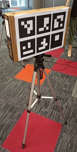
The coordinate system is better explained in the image below showing the axes drawn over a picture of the calibrator.

Figure 1 for a graphical representation
The Y coordinate origin can be changed to compensate for the actual height the calibrator is on.
- When running calibration, is the third argument
- Modify the JSON file by adding
"default_height": <height_m>
In both cases, the height is the distance between the floor and the origin of the Y axis explained above.
Adding a new board
To add a new board, the code only needs the JSON file, but other files such as the printing files or other instructions are useful to recreate the calibration board.
Flat Boards with width
When creating a new board, printing has to be done at scale 100%, the width can be changed using a simple script.
Building the Calibration Board
(e.g. A3_12_4x4_50 and A4_4_4x4_50)
Print each page of the document on the two faces of a rigid board or to opposite sides of a box. The really important part is to make sure the four corners of the board (i.e. the corner arucos) are aligned between the front and the back. See the images below for an example on how to do it using a random box.
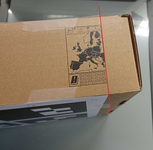
- The given files assume a width of 8cm.
Changing the reference files
# repo
python update_calibration_board.py <path/to/input_board.json> <new_width> [-o path/to/output_board.json]
python update_calibration_board.py calibration_boards/A3_12_4x4_50.json 10

# compiled
update_calibration_board.exe <path/to/input_board.json> <new_width> [-o path/to/output_board.json]
update_calibration_board.exe calibration_boards/A3_12_4x4_50.json 10
The second command will generate the JSON file for a new calibration board using a 10cm box and will be saved in the same folder with the name A3_12_4x4_50_10.json
Important notes for this script to work:
-o path/to/output_board.jsonNoneit will be stored in the same location as the input adding the_<new_width>to the name.path/to/board.json, that will be used.path/to/folder/will save with the same name as theNoneoption but in the specified folder.
- the
input_boardhas to contain the necessary information to change the width:width_axisis the index in the corner points that represents the width coordinate (x, y or z), usually it will be 1 (x)width_idsis a list with the arucos ids that are in the "back" face of the calibrator.
new_widthhas to be in the same scale as the points in the board.